Call us at (650) 856-8833 or email us at Sales@StcValve.com.
Compact Air Cylinders Dimensions
All cylinders are build to order at our China factory. Standard Lead Time: 8-10 Weeks; Option for Air Ship: 2-3 Weeks.
There are no returns on cylinders as they are custom made.
|
Aluminum Cylinders & Reed Switch |
| Model |
Picture |
Links |
Bore Size (mm) |
Stroke (mm) |
Magnet (Optional) |
Options |
| SDA Series Compact Round Cylinder |
Double Acting |
SDA |
 |
Price
Specifications |
12
16
20
25
32
40
50
63
80
100 |
5-130 |
Standard = without magnet
S = Magnet for Hall Sensor |
Thread Type Options:
Standard= Shaft with Female Thread |
| Single Acting |
SSA |
|
Mounting Hardware & Reed Switch |
| Model |
Picture |
| Reed Switch for SDA cylinder |
AL-11R-SDA |
 |
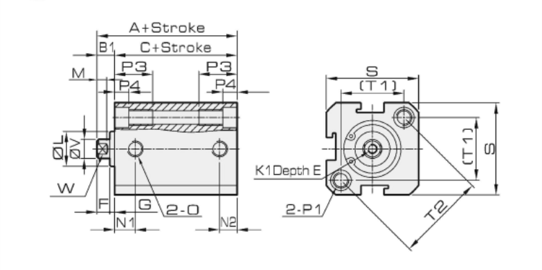
SDA 12 to 16
|
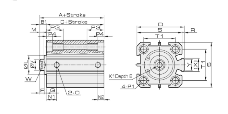
SDA 20 to 100 |
| SDA Cylinder Dimensions |
Bore /
Symbol |
A |
B |
C |
B1 |
D |
E |
F |
G |
H |
I |
J |
K |
K1 |
L |
M |
O |
| Model |
Standard |
with Magnet |
Standard |
with Magnet |
Standard |
with Magnet |
| 12 |
22 | 32 |
34 | 44 |
17 | 27 |
5 | - |
6 | 4 |
2 | 12 |
M5 x 0.8 |
4 | 8 |
M3 x 0.5 |
10 | 3 |
M5 x 0.8 |
| 16 |
24 | 34 |
36 | 46 |
18.5 | 28.5 |
5.5 | - |
6 | 4 |
2 | 12 |
M5 x 0.8 |
4 | 8 |
M3 x 0.5 |
11 | 3 |
M5 x 0.8 |
| 20 |
25 | 35 |
40 | 50 |
19.5 | 29.5 |
5.5 | 36 |
8 | 4 |
1.5 | 15 |
M6 x 1.0 |
5 | 10 |
M4 x 0.7 |
13 | 3 |
M5 x 0.8 |
| 25 |
27 | 37 |
44 | 54 |
21 | 31 |
6 | 42 |
10 | 4 |
2 | 17 |
M8 x 1.25 |
6 | 14 |
M5 x 0.8 |
17 | 3 |
M5 x 0.8 |
| 32 |
31.5 | 41.5 |
49.5 | 59.5 |
24.5 | 34.5 |
7 | 50 |
12 | 4 |
3 | 18 |
M10 x 1.25 |
6 | 17 |
M6 x 1.0 |
22 | 3 |
G1/8 |
| 40 |
33 | 43 |
61 | 71 |
26 | 36 |
7 | 58.5 |
12 | 4 |
3 | 28 |
M14 x 1.25 |
8 | 22 |
M8 x 1.25 |
28 | 3 |
G1/8 |
| 50 |
37 | 47 |
65 | 75 |
28 | 38 |
9 | 71.5 |
15 | 5 |
4 | 28 |
M18 x 1.5 |
9 | 27 |
M10 x 1.5 |
38 | 3 |
G1/4 |
| 63 |
41 | 51 |
69 | 79 |
32 | 42 |
9 | 84.5 |
15 | 5 |
4 | 28 |
M18 x 1.5 |
9 | 27 |
M10 x 1.5 |
40 | 3 |
G1/4 |
| 80 |
52 | 62 |
85 | 95 |
41 | 51 |
11 | 104 |
20 | 6 |
5 | 33 |
M22 x 1.5 |
13 | 32 |
M14 x 1.5 |
45 | 4 |
G3/8 |
| 100 |
63 | 73 |
101 | 111 |
51 | 61 |
12 | 124 |
20 | 7 |
5 | 38 |
M26 x 1.5 |
12 | 36 |
M18 x 1.5 |
55 | 4 |
G3/8 |
Bore /
Stroke |
N1 |
N2 |
P3 |
P4 |
R |
S |
T1 |
T2 |
V |
W |
X |
Y |
P1 |
| S = 5 |
S > 5 |
S = 5 |
S > 5 |
| 12 |
7.5 |
5 |
12 | 4.5 |
- | 25 |
16.3 | 23 |
6 | 5 |
- | - |
Double Size: Φ6.5, Cog: M5 x 0.8, Through Hole: Φ4.2 |
| 16 |
8 |
5 | 5.5 |
12 | 4.5 |
- | 29 |
19.8 | 28 |
6 | 5 |
- | - |
Double Size: Φ6.5, Cog: M5 x 0.8, Through Hole: Φ4.2 |
| 20 |
8.5 |
5.5 |
14 | 4.5 |
2 | 34 |
24 | - |
8 | 6 |
11.2 | 10 |
Double Size: Φ6.5, Cog: M5 x 0.8, Through Hole: Φ4.2 |
| 25 |
9 |
5.5 |
15 | 5.5 |
2 | 40 |
28 | - |
10 | 8 |
12 | 10 |
Double Size: Φ8.2, Cog: M6 x 1, Through Hole: Φ4.6 |
| 32 |
9 |
6.5 | 8 |
16 | 5.5 |
6 | 44 |
34 | - |
12 | 10 |
18 | 14 |
Double Size: Φ8.2, Cog: M6 x 1, Through Hole: Φ4.6 |
| 40 |
9 |
7.5 |
20 | 7.5 |
6.5 | 52 |
40 | - |
16 | 14 |
21 | 14 |
Double Size: Φ10, Cog: M8 x 1.25, Through Hole: Φ6.7 |
| 50 | 8 |
10.5 | 8 |
10.5 | 25 |
8.5 | 9.5 |
62 | 48 |
- | 20 |
17 | 29.5 |
19 |
Double Size: Φ11, Cog: M8 x 1.25, Through Hole: Φ6.7 |
| 63 |
9.5 | 11 |
9.5 | 11 |
25 | 8.5 |
9.5 | 75 |
60 | - |
20 | 17 |
26 | 19 |
Double Size: Φ11, Cog: M8 x 1.25, Through Hole: Φ6.7 |
| 80 |
11.5 | 14 |
11.5 | 14 |
25 | 10.5 |
10 | 94 |
74 | - |
25 | 22 |
36 | 26 |
Double Size: Φ15, Cog: M12 x 1.75, Through Hole: Φ9.2 |
| 100 |
15 | 20 |
15 | 18 |
30 | 13 |
10 | 114 |
90 | - |
32 | 27 |
35.5 | 26 |
Double Size: Φ17.5, Cog: M14 x 2, Through Hole: Φ11.3 |
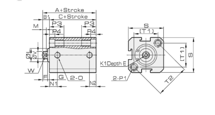
SSA 12 to 16
|
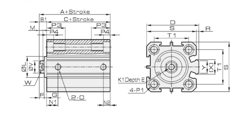
SSA 20 to 63
|
| SSA Cylinder Dimensions |
| Symbol |
A |
B |
C |
B1 |
D |
E |
F |
G |
H |
I |
J |
K |
K1 |
Bore /
Stroke |
Standard |
With Magnet |
Standard |
With Magnet |
Standard |
With Magnet |
| 0<S≤10 |
10<S≤30 |
0<S≤10 |
10<S≤30 |
0<S≤10 |
10<S≤30 |
0<S≤10 |
10<S≤30 |
0<S≤10 |
10<S≤30 |
0<S≤10 |
10<S≤30 |
| 12 |
32 | 42 |
42 | 52 |
44 | 54 |
54 | 64 |
27 | 37 |
37 | 47 | 5 | - |
6 | 4 |
2 | 12 |
M5 x 0.8 |
4 | 8 |
M3 x 0.5 |
| 16 |
34 | 44 |
44 | 54 |
46 | 56 |
56 | 66 |
28.5 | 38.5 |
38.5 | 48.5 |
5.5 | - |
6 | 4 |
2 | 12 |
M5 x 0.8 |
4 | 8 |
M3 x 0.5 |
| 20 |
35 | 45 |
45 | 55 |
50 | 60 |
60 | 70 |
29.5 | 39.5 |
39.5 | 49.5 |
5.5 | 36 |
8 | 4 |
1.5 |
15 | M6 x 1.0 |
5 | 10 |
M4 x 0.7 |
| 25 |
37 | 47 |
47 | 57 |
54 | 64 |
64 | 74 |
31 | 41 |
41 | 51 |
6 | 42 |
10 | 4 |
2 | 17 |
M8 x 1.25 |
6 | 14 |
M5 x 0.8 |
| 32 |
41.5 | 51.5 |
51.5 | 61.5 |
59.5 | 69.5 |
69.5 | 79.5 |
34.5 | 44.5 |
44.5 | 54.5 |
7 | 50 |
12 | 4 |
3 | 18 |
M10 x 1.25 |
6 | 17 |
M6 x 1.0 |
| 40 |
43 | 53 |
53 | 63 |
71 | 81 |
81 | 91 |
36 | 46 |
46 | 56 |
7 | 58.5 |
12 | 4 |
3 | 28 |
M14 x 1.5 |
8 | 22 |
M8 x 1.25 |
| 50 |
47 | 57 |
57 | 67 |
75 | 85 |
85 | 95 |
38 | 48 |
48 | 58 |
9 | 71.5 |
15 | 5 |
4 | 28 |
M18 x 1.5 |
9 | 27 |
M10 x 1.5 |
| 63 |
51 | 61 |
61 | 71 |
79 | 89 |
89 | 99 |
42 | 52 |
52 | 62 |
9 | 84.5 |
15 | 5 |
4 | 28 |
M18 x 1.5 |
9 | 27 |
M10 x 1.5 |
| Symbol |
L |
M |
N1 |
N2 |
P1 |
O |
P3 |
P4 |
R |
S |
T1 |
T2 |
V |
W |
X |
Y |
Bore /
Stroke |
S=5 |
S>5 |
S=5 |
S>5 |
| 12 |
10 | 3 |
7.5 |
5 |
Double Side: Φ6.5, Cog: M5 x 0.8, Through Hole: Φ4.2 |
M5 x 0.8 |
12 | 4.5 |
- | 25 |
16.3 | 23 |
6 | 5 |
- | - |
| 16 |
11 | 3 |
8 |
5 | 5.5 |
Double Side: Φ6.5, Cog: M5 x 0.8, Through Hole: Φ4.2 |
M5 x 0.8 |
12 | 4.5 |
- | 29 |
19.8 | 28 |
6 | 5 |
- | - |
| 20 |
13 | 3 |
8.5 |
5.5 |
Double Side: Φ6.5, Cog: M5 x 0.8, Through Hole: Φ4.2 |
M5 x 0.8 |
14 | 4.5 |
2 | 34 |
24 | - |
8 | 6 |
11.2 | 10 |
| 25 | 17 | 3 |
9 |
5.5 |
Double Side: Φ8.2, Cog: M6 x 1, Through Hole: Φ4.6 |
M5 x 0.8 |
15 | 5.5 |
2 | 40 |
28 | - |
10 | 8 |
12 | 10 |
| 32 |
22 | 3 |
9 |
6.5 | 8 |
Double Side: Φ8.2, Cog: M6 x 1, Through Hole: Φ4.6 |
G1/8 |
16 | 5.5 |
6 | 44 |
34 | - |
12 | 10 |
18 | 14 |
| 40 |
28 | 3 |
9 |
7.5 |
Double Side: Φ10, Cog: M8 x 1.25, Through Hole: Φ6.7 |
G1/8 |
20 | 7.5 |
6.5 | 52 |
40 | - |
16 | 14 |
21 | 14 |
| 50 |
38 | 3 |
8 | 10.5 |
8 | 10.5 |
Double Side: Φ11, Cog: M8 x 1.25, Through Hole: Φ6.7 |
G1/4 |
25 | 8.5 |
9.5 | 62 |
48 | - |
20 | 17 |
29.5 | 19 |
| 63 |
40 | 3 |
9.5 | 11 |
9.5 | 11 |
Double Side: Φ11, Cog: M8 x 1.25, Through Hole: Φ6.7 |
G1/4 |
25 | 8.5 |
9.5 | 75 |
60 | - |
20 | 17 |
26 | 19 |